MSP430 Project 3
What is the Inter-Integrated Circuit (I2C) protocol?
I2C is a synchronous, multi-controller/multi-target (historically termed as multi-master/multi-slave), single-ended, serial communication bus invented in 1982 by Philips Semiconductors. [1]
Each I2C device is recognized by a unique address and can operate as either a transmitter or a receiver. A device connected to the I2C bus can be considered as the master or the slave when performing data transfers. A master initiates a data transfer and generates the clock signal SCL. Any device addressed by a master is considered a slave.
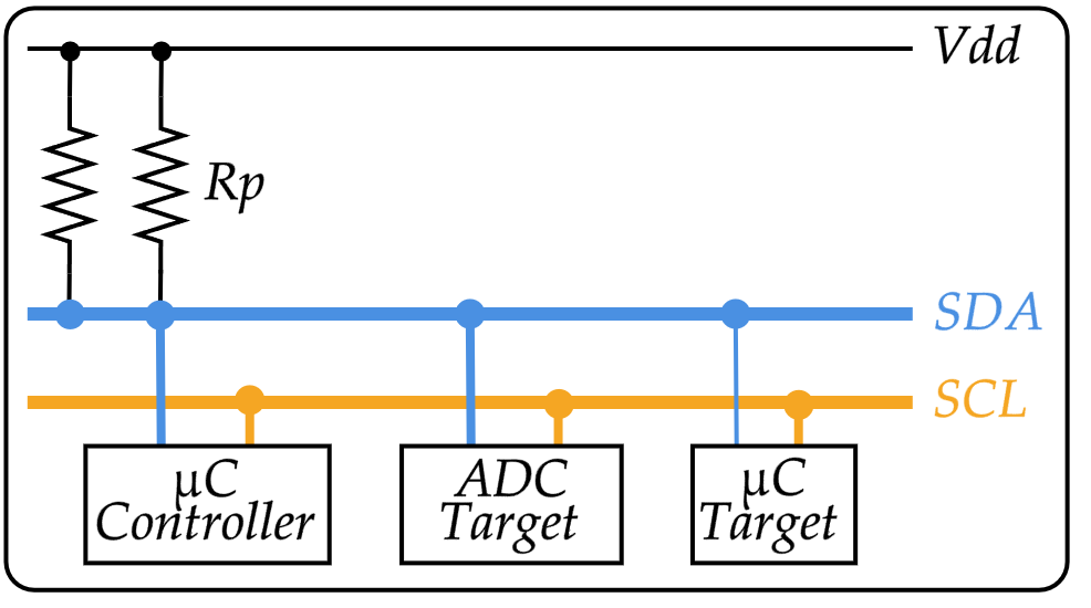
I2C data is communicated using the serial data pin (SDA) and the serial clock pin (SCL). Both SDA and SCL are bidirectional, and must be connected to a positive supply voltage using a pullup resistor.
Widely used for attaching lower-speed peripheral integrated circuits (I2C) to processors and microcontrollers in short-distance intra-board communication.
| Abbr. | Name | Description |
|---|---|---|
| SDA | Serial DAta | Serial data from master/controller. |
| SCL | Serial CLock | Clock signal from master/controller. |
| Vdd | Positive Drain Drain | Positive Supply Voltage |
Characteristics
- Synchronous (Has a clock signal).
- Multi-controller / Multi-target.
- Single-ended.
- Serial communication bus.
One particular strength of I2C is the capability of a microcontroller to control a network of device chips with just two general-purpose I/O pins and software.
Initializing
Extracted from I²C - Wikipedia ↩︎