MSP430 Project 2
Make use of Pulse Width Modulation.
What is Pulse Width Modulation (PWM)?
This references the rate of ON vs OFF of a square wave. This is done to simulate voltage level with a digital signal using a transistor/MOSFET.
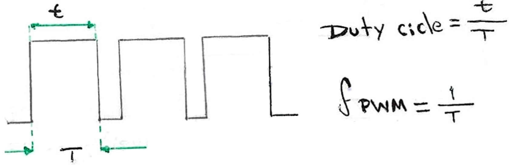
The PWM module of the microcontroller creates a square wave using a particular frequency (typically a high, like 10kHz). Then, we can change the duty cycle (% of ON state) of the signal:
From the MSP430G2xx datasheet:
Timer_A is a 16-bit timer counter with three capture compare registers. Timer_A can support multiple capture compares, PWM outputs, and interval timing. Timer_A also has extensive interrupt capabilities. Interrupts may be generated from the counter on overflow conditions and from each of the capture compare registers.
Timer_A features include:
-Configurable outputs with PWM capability
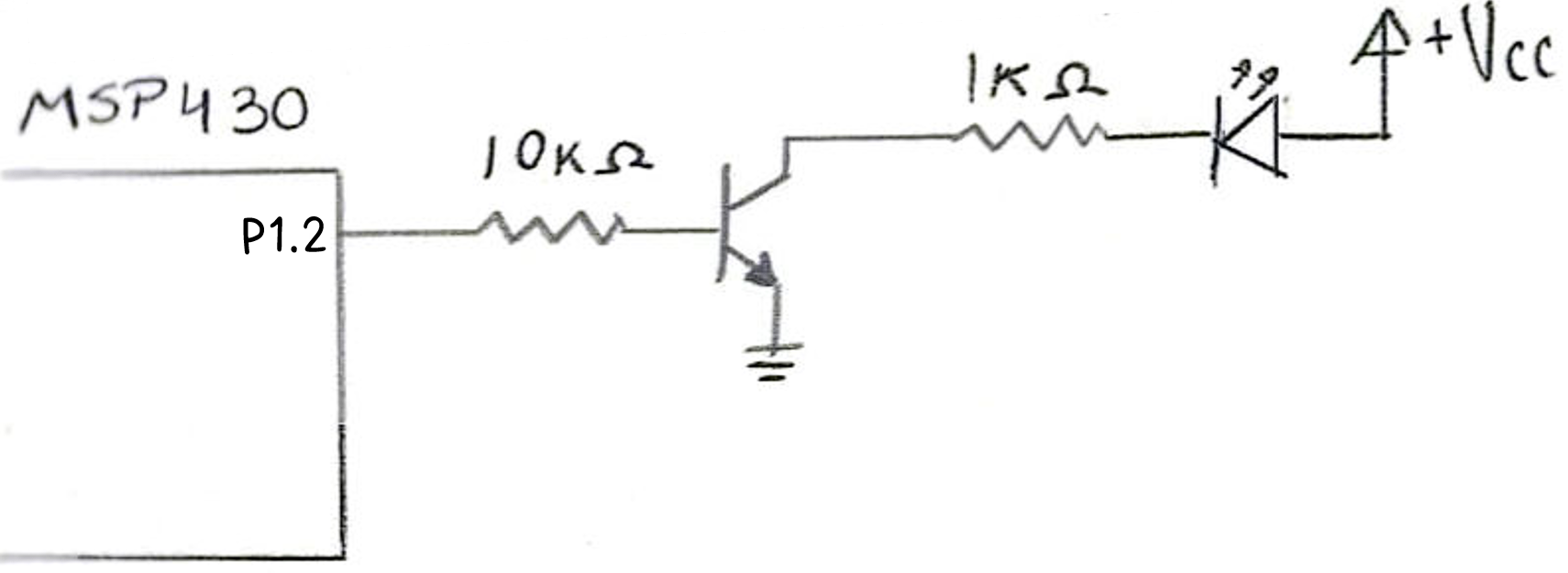
Now, we'll use a single LED and a transistor to give it enough current. Given that this PWM is at 50% duty cycle, the LED should be at MEDIUM brightness.
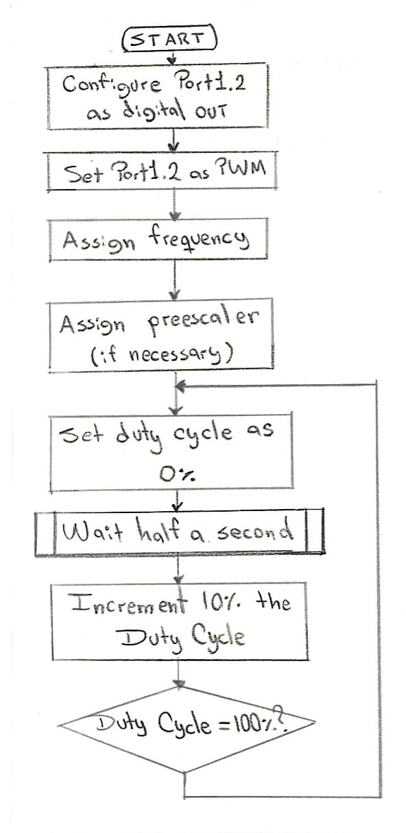
The proposed program will start from 0% brightness (or 0% Duty Cycle), increment 1% duty cycle each 0.1 seconds until it reaches 100% brightness; then it will reset to 0% brightness and wait one second before starting this pattern again.
#include "msp430g2452.h"
#include <msp430.h>

void configureClocks();
void delay_ms(unsigned int ms);
void delay_us(unsigned int us);

void configureClocks(){
    WDTCTL = WDTPW + WDTHOLD;  // Stop watchdog timer
    BCSCTL1 = CALBC1_1MHZ;     // Configure Clock to 1MHz
    DCOCTL = CALDCO_1MHZ;
 }

void delay_us(unsigned int us){
    while (us){
        __delay_cycles(1);    // 1 for 1 Mhz set 16 for 16 MHz
        us--;
    }
}

void delay_ms(unsigned int ms){
    while (ms){
        __delay_cycles(1000);  // 1000 for 1MHz and 16000 for 16MHz
        ms--;
    }
}


int main(void) {
    configureClocks();
    volatile short DutyCycle = 0;

    // Configuring Port
    P1DIR |= BIT2; // Set pin 1.2 to the output direction.
    P1SEL |= BIT2; // Select pin 1.2 as our PWM output.

    // Configuring timer for PWM
    TA0CCR0 = 1000; //Set the period in the Timer A0 Capture/Compare 0 register to 1000 us.
    TA0CCTL1 = OUTMOD_7;
    TA0CCR1 = 0; //The period in microseconds that the power is ON. To obtain the Duty Cycle, divide this value over 1000, i.e. 500/1000 = 50% Duty Cycle.
    TA0CTL = TASSEL_2 + MC_1; //TASSEL_2 selects SMCLK as the clock source, and MC_1 tells it to count up to the value in TA0CCR0.

    while(1){
        delay_ms(100);                // Delay of 0.1 seconds

        if(DutyCycle >= 100){         // Reset Duty Cycle and wait a second
            DutyCycle = 0;
            delay_ms(1000);
        }

        TA0CCR1 = DutyCycle * 10;    // Multiplied by 10 so we can use a unitary Duty Cycle
        DutyCycle += 1;              // Increment 1%
    }
}