MSP430 Project 1
Make use of pins as digital inputs and outputs.
What are GPIO?
General Pourpuse Input/Output refers to a set of pins on your microcontroller's main board. They are called that because they can be used for pretty much anything that uses digital signals as outputs or inputs.
As an example, let's first use two of this pins to turn ON and OFF two corresponding LEDs.
First, let's turn on and off two LEDs. The first LED should be ON when the second LED is OFF. There should also be a variable to monitor LED status.
#include "msp430g2452.h"
#include <msp430.h>

void main(){
    volatile unsigned int i = 1;
    volatile unsigned int LED_status;   // Create variable to supervize LED

    WDTCTL = WDTPW + WDTHOLD;           // Stop watchdog timer
    P1DIR |= 0x03;                      // Set P1.0 to output direction
    P1OUT = 0x00;                       // Initialize P1.0 as LOW
    P1OUT |= BIT1;                      // Initialize P1.1 as HIGH

    while(1){
        P1OUT ^= BIT0;                   // Toggle P1.0 using exclusive-OR
        P1OUT ^= BIT1;                   // Toggle P1.1 using exclusive-OR
        LED_status ^= 0x01;              // Toggle LED P1.0 status
        for (i=50000; i>0; i--);    // Wait
  }
}
For this circuit, we'll use 8 LEDs and 8 switches with the following configuration:
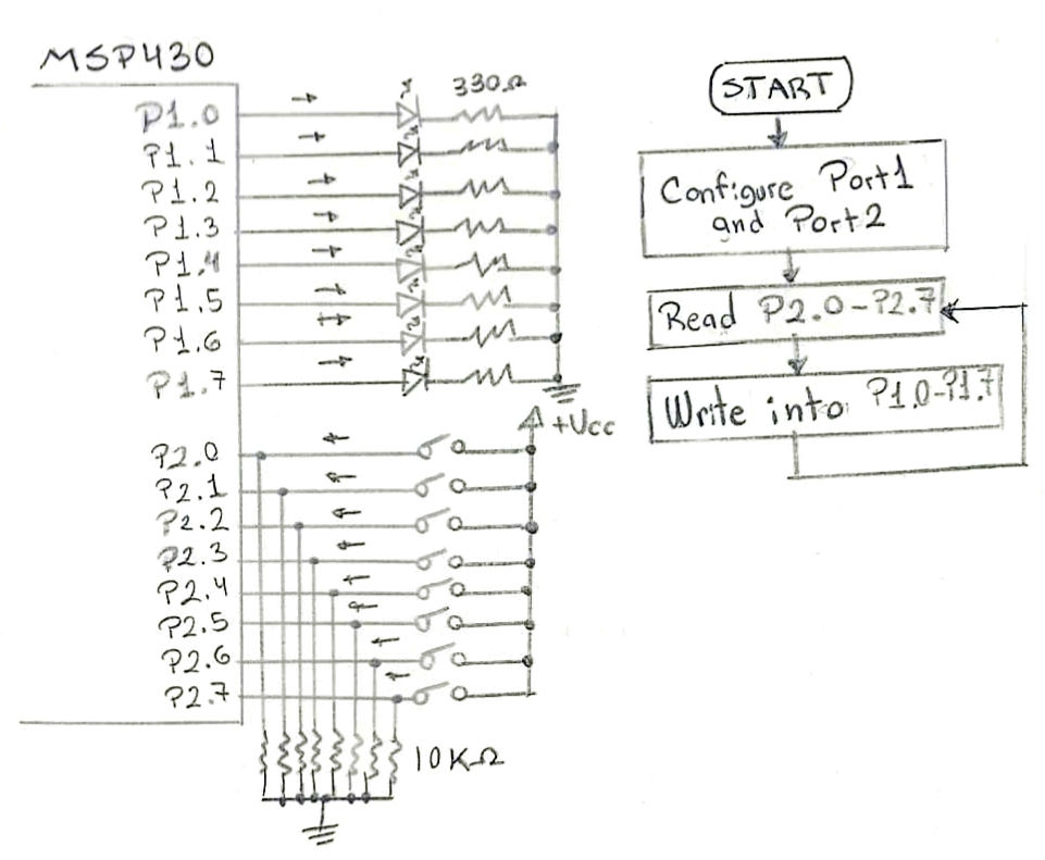
Now, we have to configure Port1 as OUTPUT and Port2 as INPUT. To achieve this, we have to configure both ports as digital IO and deactivate the additional functions from the ports.
#include "msp430g2452.h"
#include <msp430.h>

int main(void){
    volatile unsigned int i = 1;
    volatile unsigned int LED_status;

    WDTCTL = WDTPW + WDTHOLD;       // Stop watchdog timer

	// Configure ports as digital IO
	P2SEL = 0;                      // Set Port2 pins to digital I/O function
    P2SEL2 = 0;                     // Set Port2 pins to digital I/O function
    P1SEL = 0;                       // Set Port2 pins to digital I/O function
    P1SEL2 = 0;                      // Set Port2 pins to digital I/O function

    P1DIR |= 0xFF;                  // Set all of P1 bits to OUTPUT
    P2DIR &= 0x00;                  // Set all of P2 bits to INPUT

    // Configure pull down resistors on ports
    P2REN |= 0xFF;                  // Set all pull down/up resistors to ENABLE
    P2OUT &= 0x00;                  // Set resistor to pullDOWN

    initialize_routine();       // Initial routine to test LEDs

    while(1){
        P1OUT = P2IN;               // Toggle P1.0 using exclusive-OR
        LED_status ^= 0x01;
    }
}
Additionally, let's create a routine that turns on each LED in sequence so we can make sure that no LED is dead.
void initialize_routine(){
    // This routine turns all the LEDs ON one by one.
    // ----------------------------------------------
    volatile unsigned int i = 1;   // Variable for timer
    P1OUT = 0x00;                  // Initialize all port 1 bits to LOW

    P1OUT ^= BIT0;                 // Toggle bit to ON
    for (i=50000; i>0; i--);       // Wait

    P1OUT ^= BIT1;
    for (i=50000; i>0; i--);

    P1OUT ^= BIT2;
    for (i=50000; i>0; i--);

    P1OUT ^= BIT3;
    for (i=50000; i>0; i--);

    P1OUT ^= BIT4;
    for (i=50000; i>0; i--);

    P1OUT ^= BIT5;
    for (i=50000; i>0; i--);

    P1OUT ^= BIT6;
    for (i=50000; i>0; i--);

    P1OUT ^= BIT7;
    for (i=50000; i>0; i--);
}