Monostable Oscillator with Range from 0.1Hz to 100kHz
The objective of this project is to get a square wave with a variable frequency from 0.1Hz to 100kHz.
To achieve this, we'll make use of a jumper that connects different arranges of capacitors to the NE555 integrated circuit so the resulting frequency range can vary.
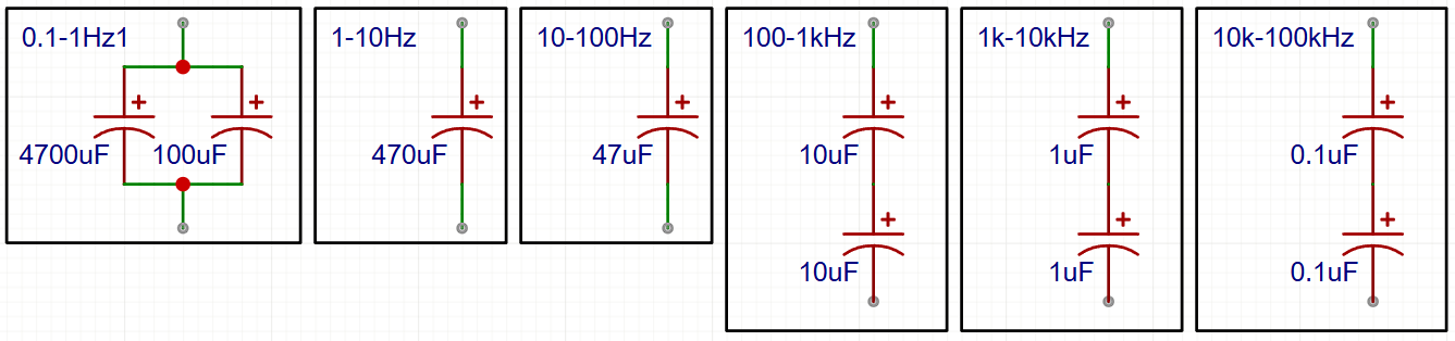
This oscillator has 6 frequency ranges.
| Range | Pin number |
|---|---|
| 0.1Hz - 1Hz | 1 |
| 1Hz - 10Hz | 2 |
| 10Hz - 100Hz | 3 |
| 100Hz - 1kHz | 4 |
| 1kHz - 100kHz | 5 |
| 10kHz - 100kHz | 6 |
In order to get this ranges, we start from the generic 555 oscillator:
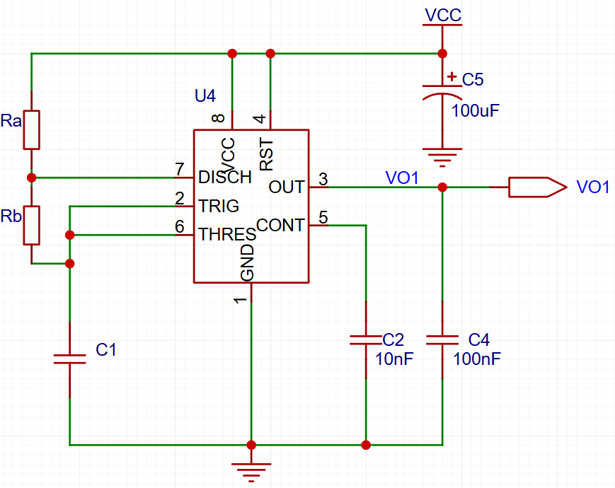
Here, the individual times required to complete one charge and discharge cycle of the output (VO1) is given by the resistors Ra, Rb and the capacitor C1 as follows:
Where, R is in Ohm’s and C in Farads.
And the frequency (T) is given as follows:
Where, F is in Hertz and T is in seconds.
We're going to start from the maximum desired frequency for the oscillator, 100kHz
From this, to make a roughly we'll divide this time between the ON time (t1) and the OFF time (t2).
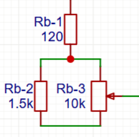
Since it's easier to variate a resistor, we'll propose two of these resistors and calculate from there the needed capacitance required to fulfill the frequency band.
And from there we need a second resistor that has a minimum value so it won't ever reach the value of zero ohms and add a variable resistor so we can go from the minimum frequency and the maximum frequency.
From here, we'll calculate each condenser so it matches the frequency range to each resistor.
Schematic
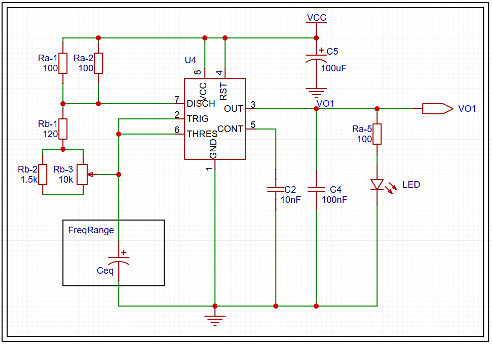
Where the frequency range is determined by a equivalent capacitor (Ceq), which is connected through a selector jumper.
| Cover | Title | Description |
|---|---|---|
| Monostable Oscillator Circuit Front Side | This is the finished 555 circuit oscillator. There is a LED indicator and an output to take that signal and use it in other circuits! | |
| Monostable Oscillator Circuito Back Side | Te back of this circuit was coated with stain to it wouldn't rust away. |